Product Description
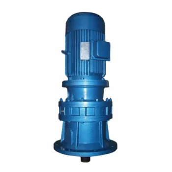
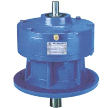
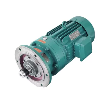
15r/m 0.385KW 150BX REA Series High Precision Cycloidal Gearbox with Flange
Model:150BX-REA-19
More Code And Specification:
| E series | C series | ||||
| Code | Outline dimension | General model | Code | Outline dimension | The original code |
| 120 | Φ122 | 6E | 10C | Φ145 | 150 |
| 150 | Φ145 | 20E | 27C | Φ181 | 180 |
| 190 | Φ190 | 40E | 50C | Φ222 | 220 |
| 220 | Φ222 | 80E | 100C | Φ250 | 250 |
| 250 | Φ244 | 110E | 200C | Φ345 | 350 |
| 280 | Φ280 | 160E | 320C | Φ440 | 440 |
| 320 | Φ325 | 320E | 500C | Φ520 | 520 |
| 370 | Φ370 | 450E | |||
Gear ratio And Specification
| E Series | C Series | ||
| Code | Reduction Ratio | New code | Monomer reduction ratio |
| 120 | 43,53.5,59,79,103 | 10CBX | 27.00 |
| 150 | 81,105,121,141,161 | 27CBX | 36.57 |
| 190 | 81,105,121,153 | 50CBX | 32.54 |
| 220 | 81,101,121,153 | 100CBX | 36.75 |
| 250 | 81,111,161,175.28 | 200CBX | 34.86 |
| 280 | 81,101,129,145,171 | 320CBX | 35.61 |
| 320 | 81,101,118.5,129,141,171,185 | 500CBX | 37.34 |
| 370 | 81,101,118.5,129,154.8,171,192.4 | ||
| Note 1: E series,such as by the shell(pin shell)output,the corresponding reduction ratio by 1 | |||
| Note 2: C series gear ratio refers to the motor installed in the casing of the reduction ratio,if installed on the output flange side,the corresponding reduction ratio by 1 | |||
Reducer type code
REV: main bearing built-in E type
RVC: hollow type
REA: with input flange E type
RCA: with input flange hollow type
Application:
Company Information
FAQ
Q: What’re your main products?
A: We currently produce Brushed Dc Motors, Brushed Dc Gear Motors, Planetary Dc Gear Motors, Brushless Dc Motors, Stepper motors, Ac Motors and High Precision Planetary Gear Box etc. You can check the specifications for above motors on our website and you can email us to recommend needed motors per your specification too.
Q: How to select a suitable motor?
A:If you have motor pictures or drawings to show us, or you have detailed specs like voltage, speed, torque, motor size, working mode of the motor, needed lifetime and noise level etc, please do not hesitate to let us know, then we can recommend suitable motor per your request accordingly.
Q: Do you have a customized service for your standard motors?
A: Yes, we can customize per your request for the voltage, speed, torque and shaft size/shape. If you need additional wires/cables soldered on the terminal or need to add connectors, or capacitors or EMC we can make it too.
Q: Do you have an individual design service for motors?
A: Yes, we would like to design motors individually for our customers, but it may need some mold developing cost and design charge.
Q: What’s your lead time?
A: Generally speaking, our regular standard product will need 15-30days, a bit longer for customized products. But we are very flexible on the lead time, it will depend on the specific orders.
Please contact us if you have detailed requests, thank you !
A
History of Cycloidal Gear System DevelopmentThe history of cycloidal gear systems dates back to ancient times, with various forms of non-circular gears being used for specialized applications. The concept of the cycloidal gear system as we know it today, however, has evolved over centuries of engineering and innovation:
The history of cycloidal gear system development reflects the contributions of many engineers and inventors who have refined and advanced the technology over time. Today, cycloidal gearboxes continue to play a crucial role in various industries and applications. pplication: |
Machinery, Robotic |
|---|---|
| Hardness: | Hardened Tooth Surface |
| Installation: | Vertical Type |
| Layout: | Coaxial |
| Gear Shape: | Cylindrical Gear |
| Step: | Double-Step |
| Customization: |
Available
| Customized Request |
|---|

How Does a Cycloidal Gearbox Work?
A cycloidal gearbox operates on the principle of cycloidal motion to transmit rotational power. It consists of a set of components that work together to achieve smooth and efficient motion transmission:
- High-Speed Input Shaft: The gearbox is connected to a high-speed input shaft, typically driven by an electric motor or another power source.
- Cycloidal Pins or Rollers: Surrounding the input shaft are a series of cycloidal pins or rollers arranged in a circular pattern. These pins interact with the lobed profiles of the outer stationary ring.
- Outer Stationary Ring: The outer ring remains stationary and contains lobed profiles. The lobes are designed in a way that allows them to engage with the cycloidal pins as they rotate.
- Motion Transmission: As the input shaft rotates, it causes the cycloidal pins to move along the circular path. The inter

Materials Used in Manufacturing Cycloidal Gearboxes
Cycloidal gearboxes are constructed using a variety of materials to ensure durability, strength, and efficient operation. Some common materials used include:
- Steel: Steel is a popular choice due to its high strength and durability. It can withstand heavy loads and provides excellent wear resistance, making it suitable for industrial applications.
- Aluminum: Aluminum is chosen for its lightweight properties and corrosion resistance. It’s often used in applications where weight is a concern, such as aerospace and robotics.
- Cast Iron: Cast iron offers good heat dissipation and is known for its high resistance to wear and shock. It’s commonly used in heavy-duty applications that require high torque and strength.
- Alloys: Various alloy combinations can be used to enhance specific properties such as corrosion resistance, heat resistance, and strength.
- Plastics and Composites: In some cases, plastic or composite materials may be used, particularly in applications where low noise, lightweight construction, and corrosion resistance are essential.
The material selection depends on factors like the application’s torque, speed, environmental conditions, and desired performance characteristics. Each material offers a unique set of advantages, allowing cycloidal gearboxes to be customized to meet diverse industrial needs.
action between the cycloidal pins and the lobed profiles of the outer ring results in a unique motion known as epicycloidal or hypocycloidal motion.
This motion generates torque that is transferred from the input shaft to the output shaft of the gearbox. The main advantage of a cycloidal gearbox is its ability to provide high torque output in a compact design. The multiple points of contact between the pins and the lobes distribute the load, enhancing the gearbox’s load-carrying capacity.
Cycloidal gearboxes are known for their smooth and controlled motion, making them suitable for applications requiring precise positioning and high torque capabilities, such as robotics, automation, and industrial machinery.


editor by CX 2023-08-17